XD6 Hardware Interfaces
This section describes the characteristics and operation of all connectors on the XD236 and XD1036.
Ethernet/PoE
An RJ45 jack is provided for connection thatsupports 10/100/1000 Base-T operations, as well as Power over Ethernet (PoE). This ethernet connection delivers power on PoE type 2 and is rated to 25W, providing the upstream Ethernet power feed supports this higher power class.
A second RJ45 jack that supports 10/100/ Base-T operations provides a non-PoE network connection. It is intended to create an internal network amongst a number of screens for the purpose of screen identification and control. It is for screen control only (DNS relay is not supported).
802.1x is only supported on the primary ethernet port, and not on secondary ethernet ports or USB-connected ethernet devices.
Power Connector
The power connector for the XD236/XD1036, which connects the power cord to the device, is rated for 12V @3A. When looking directly at the device's power socket, right-side positive power:
- Ground signal is the pin nearest to the edge of the product
- 12V power signal is the pin nearest the push buttons
HDMI Output
The HDMI-out connector is used to send digital video and audio to HDMI-enabled sink devices. The HDMI® output on the XD236/XD1036 is HDMI 2.0a.CEC control is supported over the HDMI interface independently.
The XD236/XD1036 support HDR video as well as:
- 3840x2160x60p 10-bit video decode and display
- Dual 3840x2160x60p 10-bit video decode and playback
- 3840x2160x60p video rotation
- 3840x2160 graphics plane resolution support
GPIO
XD236/XD1036 players have a 12-pin GPIO switch and an LED connector, which allows the player to control external LEDs or other devices or other devices requiring 24mA of current or less.
The GPIO port is a standard design manufactured by Phoenix Contact, Wurth Electronics, and others. Pluggable GPIO terminal blocks can be inserted into the GPIO connector to make bare-wire contacts (see here for an example part). These terminal blocks can be purchased from the BrightSign Store. If you wish to source your own terminal blocks, make sure to use 4-pin or 6-pin blocks (12-pin blocks are extremely difficult to remove from the GPIO port).
Connect the LED outputs to the LED ANODE and connect the LED CATHODE to the ground. If you want to connect another device, then the output is capable of sourcing or sinking up to 3.3V at 24mA, but there is a series resistor of 100Ω in each line.
The GPIO also allows for connecting of external contact closures to the ground. In order to connect a switch, connect one side of the switch to the switch input, and connect the other side to one of the ground pins on the GPIO connector. The connector can also supply 3.3V at up to 500mA to an external device. The 3.3V output is polyfuse-protected and can source up to 500mA.
If one BrightSign player is driving the inputs on another BrightSign player, then you can drive at most three inputs from one output. The following calculations explain this limitation:
The GPIO outputs have 100Ω series resistors; the GPIO inputs have 1K pullup resistors to 3.3V; and the input threshold is 2V high and .8V low. The high voltage is not problematic, but the low voltage can be if there are too many inputs connected to one output.
| |
|---|---|
1 out driving 1 in | V=3.3*100/(100+1,000)=0.3 |
1 out driving 2 in | V=3.3*100/(100+500)=0.55 |
1 out driving 3 in | V=3.3*100/(100+333.3)=0.76 |
1 out driving 4 in | V=3.3*100/(100+250)=.94 (This is too high, so 1 output driving 3 inputs is the maximum) |
GPIO Pinout
The following table illustrates the pinout of the GPIO on the XD236 and XD1036:
Pin | Function | Pin | Function |
|---|---|---|---|
1 | GND | 7 | GND |
2 | 3.3V | 8 | 3.3V |
3 | BUTTON 0 | 9 | BUTTON 4 |
4 | BUTTON 1 | 10 | BUTTON 5 |
5 | BUTTON 2 | 11 | BUTTON 6 |
6 | BUTTON 3 | 12 | BUTTON 7 |
The following schematic illustrates the pinout of the GPIO connector.

IR Input / Output
The IR blaster generates or receives a space-encoded NEC or Pronto Hex signal. The two transported bit values of the signal (0 and 1) are encoded using differing lengths of low-time IR pulses.
The 3.5mm IR in/out port has the following pinout:
- Tip: 3.3V@50mA
- Ring: IR Input
- Sleeve: IR Output
The sleeve is used as a ground during input operations.
Serial Input / Output
The XD1036 has a UART (asynchronous serial) interface in a 3.5 mm mini-jack that uses RS-232 levels for communication. This 3.5mm serial connector uses standard RS232 (signal) levels and polarities.
The default baud rate of the interface is 115200, with no parity, 8 data bits, and 1 stop bit. These settings can be configured in the software. The serial interface supports TX, RX, and ground only—RTS/CTS hardware flow control is not supported. The following diagram illustrates the behavior of the TX and RX signal:

The 3.5mm serial port has the following configuration (from the perspective of the player):
- Tip: Receive
- Ring: Transmit
- Sleeve: Ground
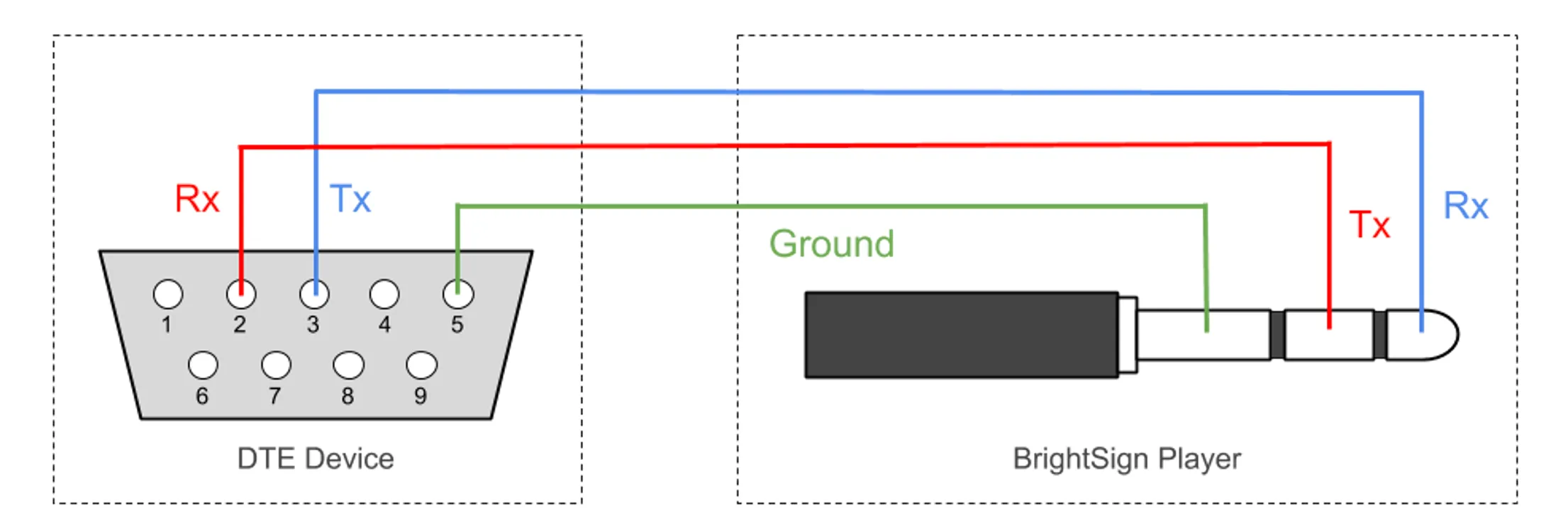
BrightSign players are DCE devices, so communication with another DCE device that uses a 3.5mm port would require a null-modem cable or converter that transposes the TX/RX signals. If the device communicating with the player is a DTE device with a DE9 serial port (performing asynchronous transmission), the serial cable should be wired as shown in the following diagram:
The XD236 does not support Serial I/O.
Audio Connector
The XD236/XD1036 have a combination have a combination analog/optical audio jack. To transmit a digital audio signal, use a TOSLINK optical audio cable with a 3.5mm connector. Analog and digital audio cannot be transmitted simultaneously.
The full-scale voltage output of the analog audio is 2V RMS. The minimum load impedance is 32Ω.
The analog audio connector has the following pinout:
- Tip: Left audio
- Ring: Right audio
- Sleeve: Ground for audio signal
USB
The XD1036 has one USB-A and one USB-C port to connect USB-compatible devices. The USB-C port supports both device and host mode and USB-C to any GPIO Panda device. Both ports meet USB 2.0 specifications.
The XD236 does not support USB ports.
WiFi & Antennas
XD236/XD1036 players are equipped with an E-key M.2 connector which supports 2230 form factor M.2 cards for WiFi (PCIe interface) and Bluetooth[CW1] (USB interface) connectivity. The recommended card is sold separately as BrightSign WD-105 kit which includes two internal antenna cables and two external antennas which are fitted to the external SMA connectors. The internal cables are pre-attached to the card (IPEX4 MHF4 type) and must also be attached to the motherboard connectors (IPEX MHF 4L Type) behind the SMAs.
Cellular Modem
XD236/XD1036 players are fitted with a B-key M.2 connector which supports 4230 form factor M.2 cards for cellular modem (USB interface) connectivity. The recommended card is the Quectel EM05-G IoT/M2M-optimized LTE Cat 4 module. The external SMA connectors can be used to mount two 4G/5G antennas appropriate for the region of intended use. Two internal cables with appropriate connectors will need to be sourced to connect the card to the antennas.
A nano size SIM card socket is located on the PCB Assembly. The player supports the EM05-G cellular module.
SSD Interface
XD236/XD1036 players will accept NVMe SSDs in M.2 2242 or 2280 (but not 2260) form factors of SX id type (single-sided form factor). Double-sided drives (DX id type)* will not fit because the back side of the SSD is essentially flush against the motherboard. For example, a 2280-S1 module will fit a BrightSign player but a 2280-D2 module would not.
NVMe drives with heat sinks are not compatible with our players. _______________
*D4 drives may fit but have not been tested